Difference between revisions of "03 Motor gondola"
| Line 62: | Line 62: | ||
[[File:motor16.JPG|400px]] | [[File:motor16.JPG|400px]] | ||
| + | |||
| + | [[:File:motor_glue.jpg]] | ||
Now it´s time to glue! Every other plastik modell glue will probably do it as well. Epoxy however works great. | Now it´s time to glue! Every other plastik modell glue will probably do it as well. Epoxy however works great. | ||
Revision as of 14:47, 7 December 2015
Back to overview: tutorial_i4
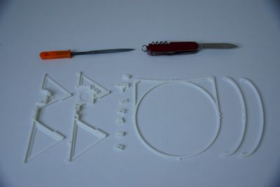
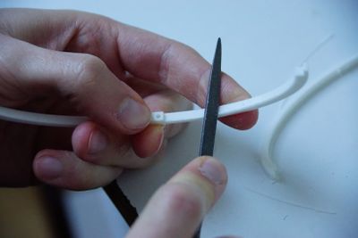
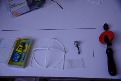
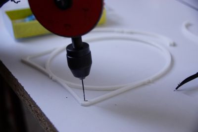
First the plastik parts need to be prepared by removing the remains of the printing process. This can be done with a knife and a fine rasp.
For the motor gondula, the two bows and ring have to be prepared. Open the center holes for the screws and remove all remains from the printing process.
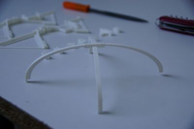
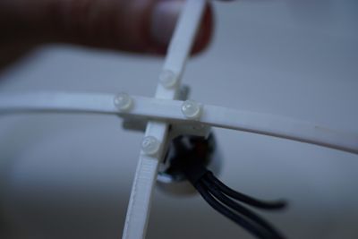
The two bows form a cross like seen in the picture.
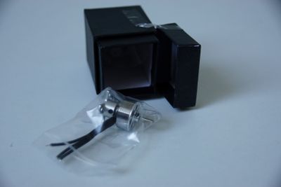
Now the motor can be unpacked.
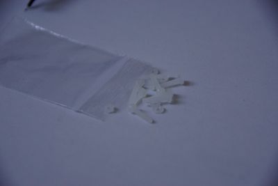
For the coming steps you´ll need glue, the prepared plastik parts of the motor gondula, the tiny plastik screws. Maybe you need the drill again to open the holes for a perfect fit.
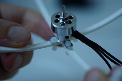
To attach the motor you´ll need 4 of the screws and 4 nuts.
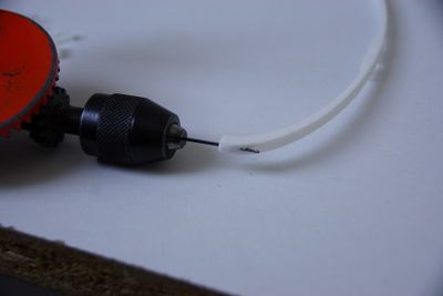
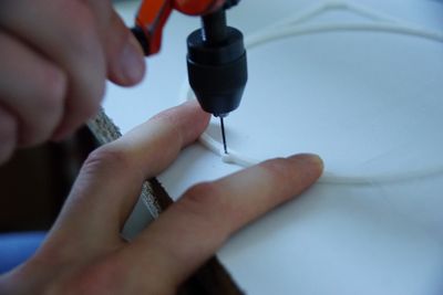
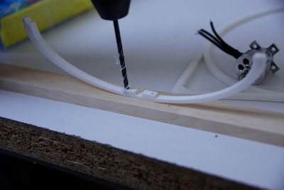
Use the 1 mm drill to open the hole in the vertical bow. Later the longest (45 cm) of the 1 mm CFK rods has to fit here.
This whole of the motor ring is where the longest (45 cm) CFK rod has to go in as well.
The holes at the left and right side of the motor ring are used for the shorter (40 cm) cfk rods.
Make sure the wholes are wide enough to get the screws in. Maybe using a 2.5 mm diameter drill fits better.
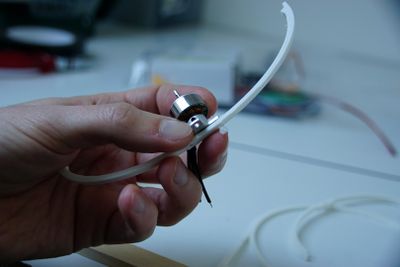
Connect the horizontal bow first using the two screws.
Then connect the vertical bow, using two other screws.
Put the nuts in place.
Don´t fix them too strong, since this plastic screws are light-weight on the one hand but not that strong on the other hand.
By slightly adjusting the nuts the angle of the motor can be defined later if the propeller hit´s the motor ring.
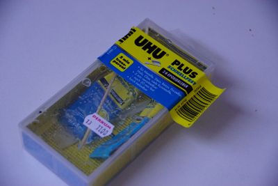
Now it´s time to glue! Every other plastik modell glue will probably do it as well. Epoxy however works great.
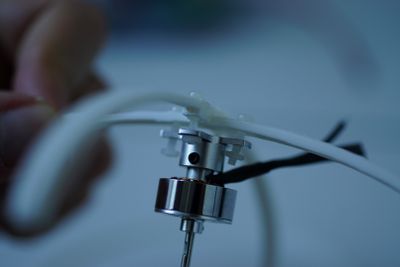
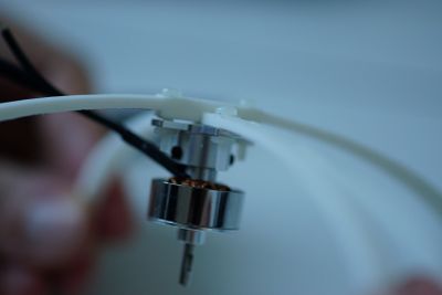
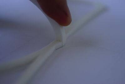
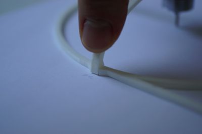
Glue the horizontal bows in place. (right)
Glue the horizontal bows in place. (left)
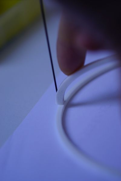
This part of the motor ring is just fixed to the vertical bow by pushing through the long (45 cm) carbon rod. No glue is used here. This way you can change the angle of the carbon rod to perfectly adapt the motor gondola to the hull. The opposite part of the vertical bow needs to be glued, like the left and right.
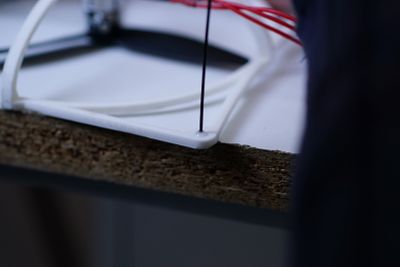
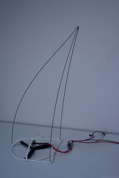
The two shorter (40 cm) cfk rods go now in the remaining holes of the motor ring on the left and right side. They need to be glued in place. A little drop of glue is enough.
This is how it should look like now. The propeller is not really needed at the moment.
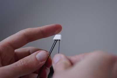
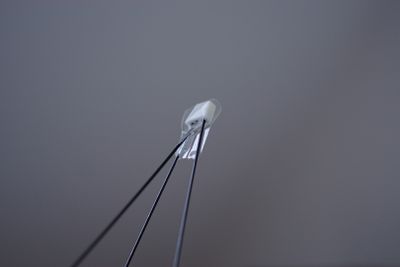
Let the glue dry and after that place the little printed part that connects the 3 CFK rods. Maybe you need to open the wholes of this part first, using a 1 mm drill. Use a bit of glue to fix all the carbon rods here.
You can fix the carbon rods using some tape. Usually they stick in rather well and you don´t need the tape.
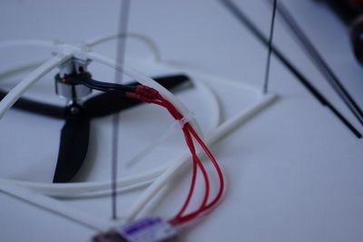
Once the ESC is soldered to the motor you can use a cable tie to fix the wires in position. This step can be performed after the electronics are done.
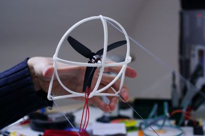
This is the final motor gondola, the ESC however will be connected in the next part of the building process: 04_Electronics
