05 Cross fins
Back to overivew: tutorial_i4
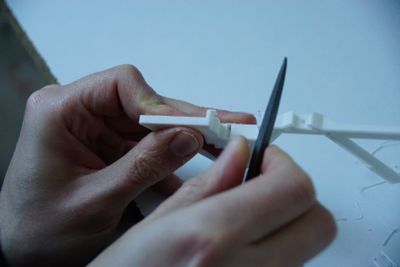
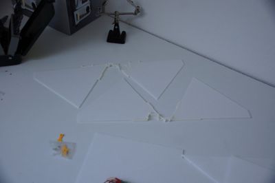
The remaining plastik parts are used for the fins. If not already done, clean them from the printing process.
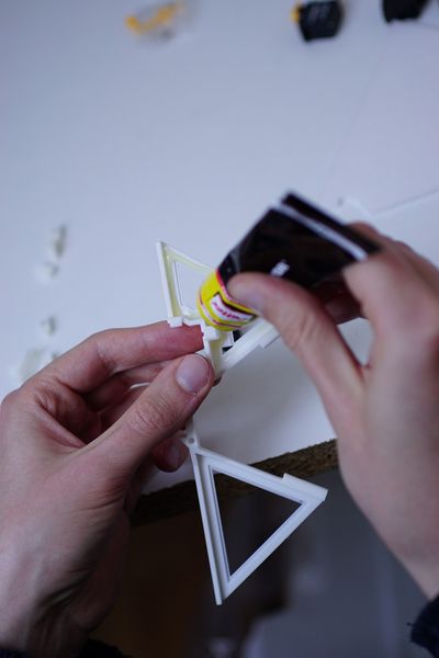
First we glue the not moving depron parts to the plastik. You can use any glue that is suiteable for styrofoam. Refere to the instructions of the glue on how to use it in the best way.
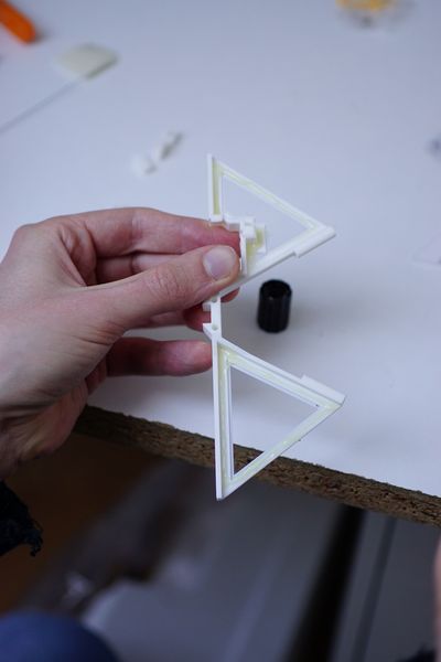
Put the glue everywhere on the plastik parts, where in a moment the depron parts are inserted.
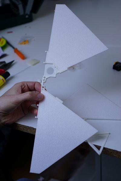
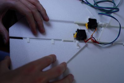
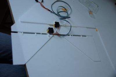
Put the depron parts in place like seen in the picture.
Do that for both, the horizontal and vertikal part of the cross fins.
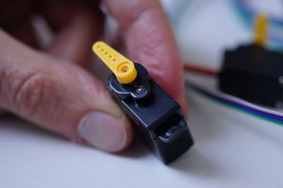
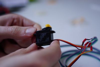
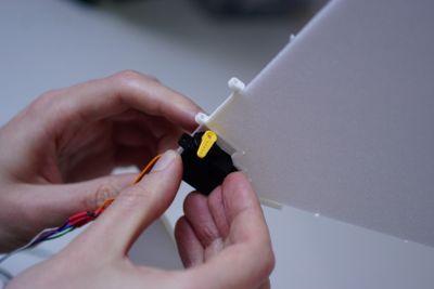
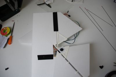
The vertical servo needs a bit of manipulation for a good fit. Remove the little plastik knob on the top, using a knife or a file.
This is how it looks after removing the knob.
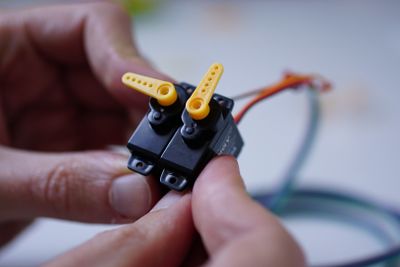
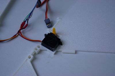
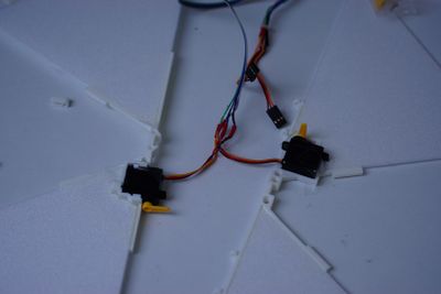
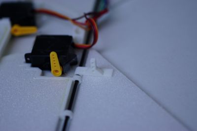
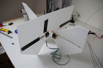
Now the position of the servo horns need to be fixed. It´s a bit tricky to remove them once they are fixed in the cross fins. So it´s good to center the servos now and connect the yellow servo horns. The horizontal servo for the elevator is the left one in the picture and it´s horn needs to be fixed to 90°. The right servo in the picture is the vertical one for yaw. This servo horn needs to be straight.
To check this, you can connect the servos to the receiver, power the whole system using the ESC and battery and set the remote control channels to center position. Now fix the servo horns like shown in the above image.
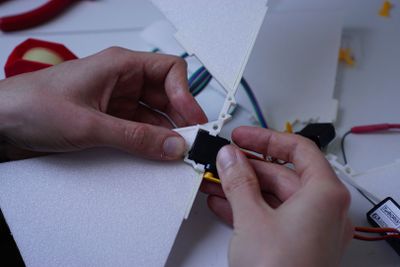
After setting the servo horns to the right positions, the servos will be glued in place. To do that use Epoxy glue over the whole servo fitting area of the printed parts.
Glue in the vertical servo for yaw.
Glue in the horizontal servo for the elevator.
This is how the horizontal servo for the elevator should look like.
This is how the vertical servo for the yaw should look like.
Let the whole setup dry to prepare the next step, which is the construction of the elevator rudder.
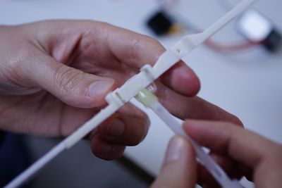
The elevator rudder has a left and a right depron part. They are connected to the 2 mm CFK rod using the little printed parts. The servo controls the elevator rudder using the printed servo horn which needs to be placed next to the servo.
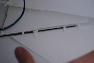
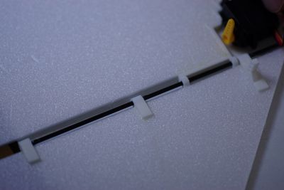
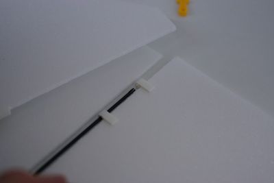
Find the right positions for the little plastik parts at the right elevator part.
Also find the right positions at the left part. Make sure the CFK rod easily rotates in the holes of the fixed part of the fin. The CFK rod moves freely in these holes, while it´s glued to the elevator rudder parts.
Make sure the plastik servo horn is on the same line with the servo.
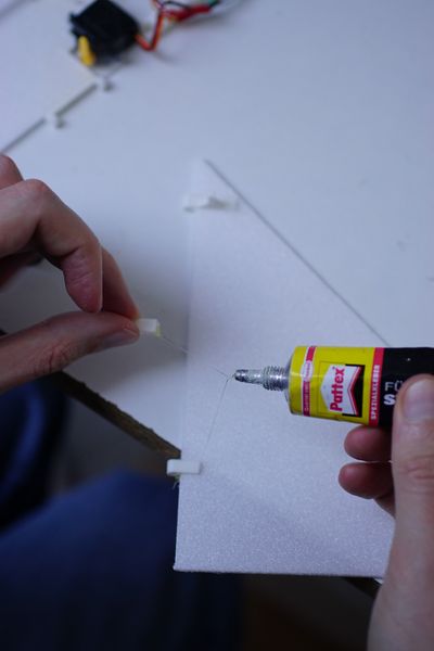
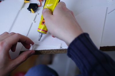
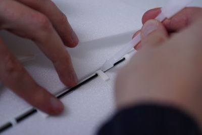
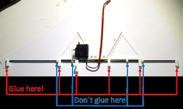
Now glue all the little plastik parts in position using styrofoam glue. Epoxy actuall works as well.
Do that also for the plastik servo horn.
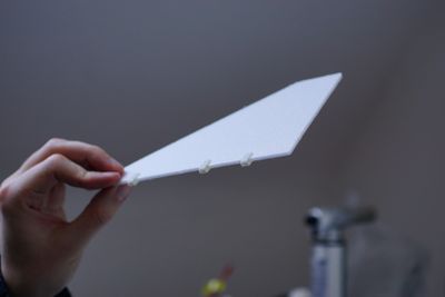
This is how the parts should look like. During the glueing process you can insert the 2 mm CFK rod, to make sure that the plastik parts are positioned correct.
Now place the two parts of the elevator rudder next to the horizontal counter part of the fins. And gently slide the CFK rod through all the wholes.
Shift the whole elevator rudder parts a little to the left and right to insert the glue to the little plastik parts. This way you can fix the two elevator parts to the CFK rod.
Glue like this to enable the elevators movements.
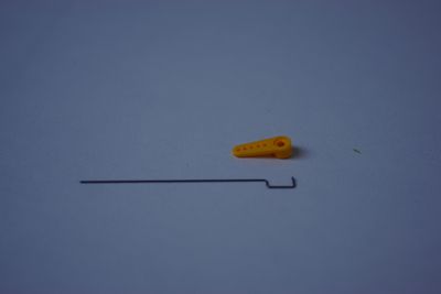
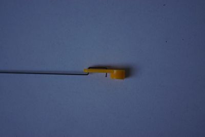
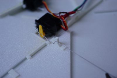
While the Epoxy is curing you can prepare the steel wires that connect the servo horns with the moving rudders. Use pliers to form the wire for the yaw rudder like seen in the picture.
Use the holes of the servo horn as a template. You can also use one of the other servo horns that come with the package but are not used.
Now bend the other steel wire as seen in the picture to connect the horizontal elevator servo with the moving part.
Within the next step, the 4 remaining 1 mm CFK rods are prepared.
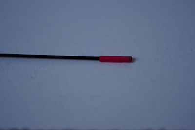
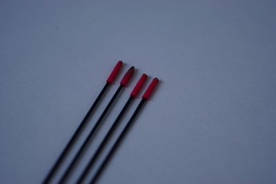
Use a piece of the heat shrink tube on the one side of the CFK rods. This protects the envelope of the airship from the pointy tips of the rods.
Do that for all 4 remaining 1 mm CFK rods.
Let´s continue with the vertical yaw rudder.
Use tape to connect the remaining big depron part to the vertical part of the fin like seen in the image. The wire from the servo horn is covered by tape as well, which gives direct control for the yaw rudder.
Put tape on both sides of the rudder and make sure the rudder can move 45° to left and right.
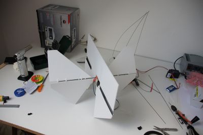
Now the crossfins are ready for testing! Put them together in the center. You can fix that assembly using one of the tiny plastic screws.
Connect the servos to the receiver to test if the servos move in the right direction. If not, swap them on the receiver or sender. Now everything is ready to inflate the envelope with air and rig the whole airship the first time: 06_Envelope
