04 Electronics
Back to overview: tutorial_i4
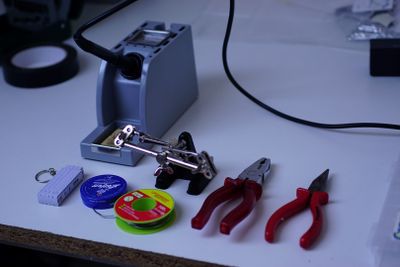
Prepare your soldering tools.
In this step of the tutorial we´ll cover how to connect the ESC to the motor and how to solder the 2 micro servos. You need: ESC, battery connector wire, 2x micro Servo, 4 wire boundle, heat shrink tube
Cut the heat shrink tube in about 1 cm long pieces to later protect the soldering joints against shortcuts.
Warm up your soldering tool. About 360°C are a good temperature value.
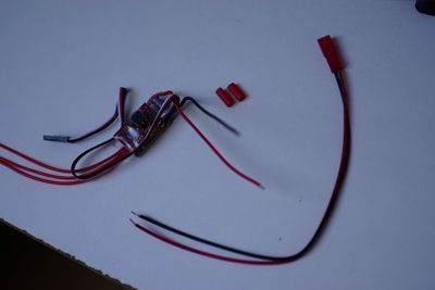
Prepare the parts to connect the battery plug to the ESC: ESC, Battery plug cable, 2 heat shrink tube pieces
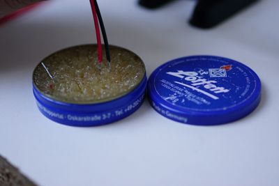
Cover the end of the cables in soldering flux, this makes soldering much simpler and nicer. And put the heat shrink tube pieces over the two wires.
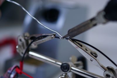
Connect the black wire of the ESC to the black wire of the battery plug.
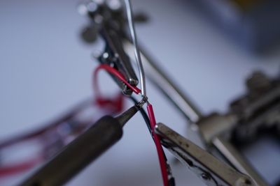
Connect the red wire of the ESC to the red wire of the battery plug.
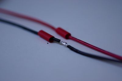
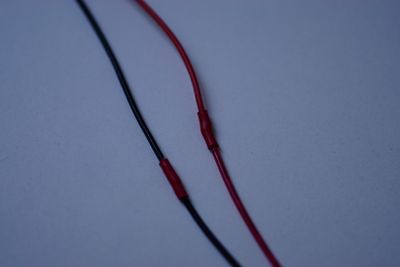
Cover the soldering joints with the heat shrink tube.
Use a lighter, a candle flame or whatever hot you have to shrink the tubes.
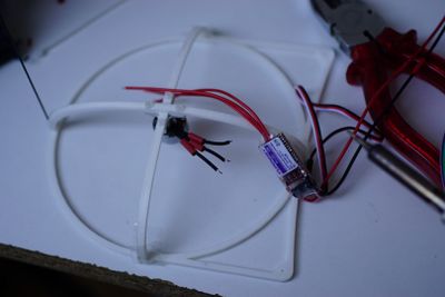
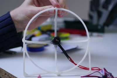
Now the motor gondula comes into the game. Put the heat shrink tubes to the three wires.
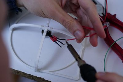
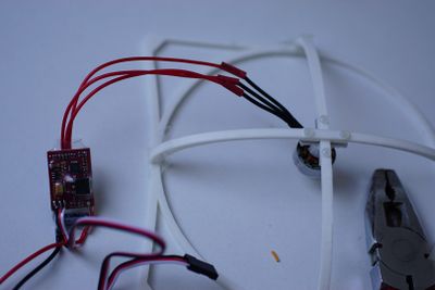
Solder the 3 red wires of the ESC to the wires of the motor. Be aware to keep the hot soldering iron away from the plastik parts, since they don´t like hot temperature.
Do not shrink the tubes to the cables yet! First we need to test in which direction the propeller runs. If the propeller spins in the wrong direction, two of the ESC wires have to be swapped.
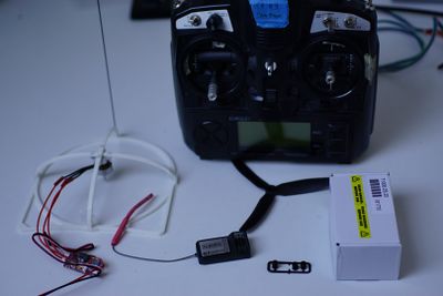
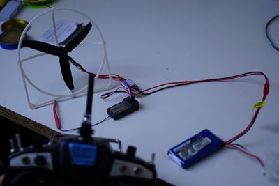
To test the motor you need the following stuff: Motor gondula, receiver, remote control, propeller, LiPo battery
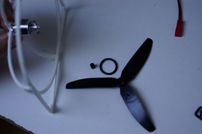
Use the rubber ring and the little black fitting ring to plug the propeller on the spinner of the motor.
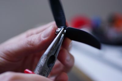
If you don´t have the right screwdriver, you can use a plier to fix the screws of the motor spinner.
Make sure the propeller turns freely inside the plastic protection ring. You can adjust the angle of the motor by the 4 plastic screws that connect it to the bows.
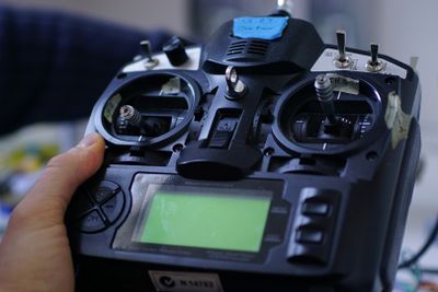
To test the motor, you need to connect the ESC to the receivers motor channel and switch of the remote control. Then you can power the system with the LiPo battery, which is connected to the ESC.
During power on, keep the motor channel at the lowest position, until a few beeps indicate that the motor is ready. Now slowly raise power and check if the motor runs in the right direction. If not, swap two of the 3 wires that connect ESC and motor and solder them again. This will change the turning direction.
If everyhing is right you can check the motor with full throttle. Attention! It has quite a lot of power!
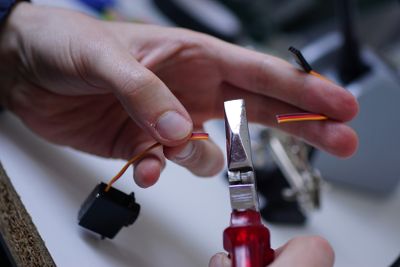
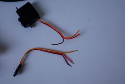
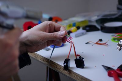
Now the motor gondula is ready and we work on the servos for the cross fins. First you need to cut of the plugs of both servos in the middle of the wire.
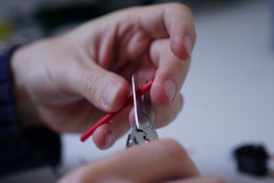
Use a plier to cut the servo wires of.
Remove the cover of the wires at the tips for soldering.
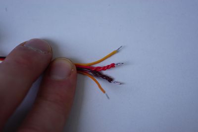
Drilling the sub-wires together makes it easier to solder them.
Since the two servos share the same power lines (black and red wire) to save some weight, they will be connected to the same wire of the long boundle. It´s easier to solder if you drill the two black and the two red wires to each other. Do that with the servos and with the plugs of the servo.
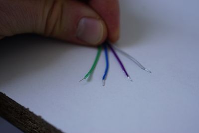
Now prepare the both ends of the long 4 wire boundle.
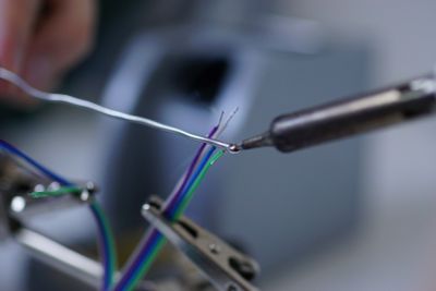
If you put a little soldering flux onthe tips of the wires and then a little bit of tin, they will be simpler to solder.
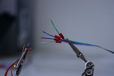
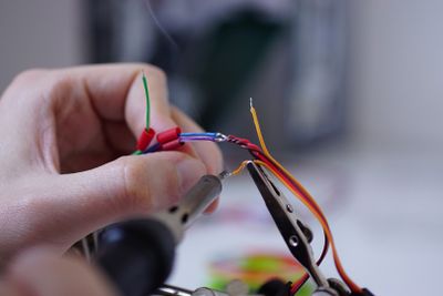
Don´t forget to put 4 heat shrink tubes over the wires before soldering. Now connect the red, the black and the two yellow wires to the long 4 wire cable. Be aware that the same colors of the long cable are connected on the servo and on the servo plug side.
Soldering is much easier if you use a such a soldering tool with clips.
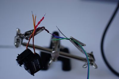
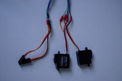
This is how it should look like on the servo end. Both servos are connected to the long 4 wire cable.
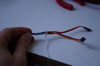
Now we solder the opposite part of the long cable to connect the two servo plugs. Do it the same way like the servos and make sure that the colors are right. Black-> Black, Red->Red, Yellow->Yellow.
This is how the servo plug part should look in the end. This part will be connected to the receiver. Use a cable tie to strengthen the soldering joints.
Now the long cable is ready and connects the servo plugs on the receiver with the two servos that will now be used in the crossfin layout: 05_Cross fins
